Metal tensile test according to EN ISO 6892
Metal tensile test according to EN ISO 6892
The tensile test of metalic materials is further divided into:
EN ISO 6892-1 Metallic materials - Tensile testing - Part 1: Test method at room temperature
EN ISO 6892-2 Metallic materials - Tensile testing - Part 2: Test method at elevated temperature.
EN ISO 6892-3 Metallic materials - Tensile testing - Part 3: Low temperature test method.
EN ISO 6892-4 Metallic materials - Tensile test - Part 4: Liquid helium test method
Tensile testing according to EN ISO 527 covers the testing of a wide range of plastics - filled or unfilled materials, molded or cast samples, foils and plates, as well as fiber or binder reinforced materials.
The tensile test according to EN ISO 6892 is the basis for other tests which have the same/similar principle: e.g. EN ISO 898 (tensile test for bolts), DIN 488 (reinforcing steel for concrete parts) and other standards.
In principle, tensile testing is identical to tests on parts, products, assemblies, components, tensile testing of plastics, tensile testing of elastomers/rubber, but not described here.
This article only refers to EN ISO 6892-1, which is the most commonly used standard for tensile testing of metallic materials.
Tensile test of metallic materials
The tensile test of metallic materials according to EN ISO 6892 always considers a homogeneous cross-section as the initial situation. In the tensile test, the clamped specimen is loaded (stretched) very slowly, especially at the beginning of the loading in a very sensitive, elastic region (reversible deformation - elastic elongation). One of the most important areas of the tensile test is the transition between elastic and plastic deformation, and it is therefore important that the test speed is constant in this area. Later in the plastic region (permanent, irreversible deformation) the test speed may increase. The tensile test ends when the material breaks - by breaking the specimen into two pieces or when another set criterion for the end of the test is reached.
Achieving correct and reliable results, however, does not begin with the tensile test itself, but with the production of the tensile test specimen. Production must be accurate and in accordance with the standard.
Requirements for tensile test according to EN ISO 6892
- Tensile testing machine class 1 according to ISO 7500
- Clamping fixtures, jaws appropriate to the material and size of the specimen
Extensometer (strain gauge) according to budget
- hand-held, hand-held strain gauge - usually with a small stroke for the determination of Rp 0,2 and E-modulus
- automatic strain gauge - for determining Rp 0.2, E-modulus and also tensile strength at maximum tension as well as fracture toughness
- non-contact video-extensometer - for determination of Rp 0,2, E-modulus and also tensile strength at maximum stress as well as fracture toughness
- using the features on the sample itself
Tensile test procedure
EN ISO 6892 - Method A
EN ISO 6892 recommends that tensile testing of metals should be carried out according to method A. In this test, the specimen is elongated in a defined way. In the elastic region (the origin of the graph where there is a straight, level ascending line) the specimen must be stretched slowly to accurately capture any changes, as in this sensitive region a higher test speed may distort (increase) the measured values. According to EN ISO 6892 a test speed of 0,000 25 mm/mm/s is to be used. However, the resulting test speed also depends on the initial measured length.
In the elastic region of the tensile test, the controlling variable obtained by the strain gauge (change in the magnitude of the distance of the strain gauge blades per second) is the elongation of the specimen (so-called closed control circuit). For example, for a cylindrical specimen with a diameter of 10 mm and an initial measured length of 50 mm, the test speed is thus converted to the resulting speed: 0.00025 mm x 50 mm = 0.0125 mm/s (0.75 mm/min).
If the specimen is made of a material with a significant yield strength ReH, the strain gauge could get into a very unstable situation (alternating loosening and strengthening of the material at the yield point). Based on this fluctuation, the strain gauge could find it very difficult to control the load speed if its data channel is still used to control the machine. The standard allows for this situation and therefore in the next part of the test the controlling variable is not the elongation increment but the crosshead speed of the test machine. The test speed at the yield point (ReH, ReL) is left at 0,00025 mm/mm/s. Since the extensometer as a control element loses its importance, the loading speed is no longer calculated on the basis of L0 but on the basis of Lc (the distance between the curves on the specimen). In our case, we used a cylindrical specimen with a diameter of 10 mm and so the resulting test speed is (in the open control circuit: 0.000 25 mm x 60 mm = 0.015 mm/s (0.9 mm/min). As soon as the stress rise has stabilized (beyond a significant yield strength), the machine switches to the increased test speed.
If the material is tested without a significant yield strength or after overcoming the yield strength, the velocity increases as smoothly as possible to 0.0067 mm/mm/s after exceeding the value Rp1.0, e.g. at 1.2% elongation, during this transition to the plastic region. Since in the next part of the test, a partial constriction or narrowing at fracture (formation of a neck when exceeding Fmax) may occur outside the blades of the strain gauge (the strain gauge does not register any increment because the specimen is extended beyond the measured distance), the strain gauge is not used for machine control in this part, but the machine control is based on the displacement of the crossbar (open control circuit). Therefore, the test software does not work with the L0 value of the strain gauge (i.e. 50 mm in this case) when calculating the test speed, but with the value of 60 mm, which is the value between the curves on the sample: 0.0067 mm/mm/s x 60 mm = 0.402 mm/s (24.12 mm/min).
EN ISO 6892 - Method B
This method is possible if the machine does not allow direct control by means of a closed control circuit and is more in line with the original EN ISO 10002. The point is that the specimen is not loaded at a constant speed based on the deformation of the specimen, but on the stress rise, i.e. the method considers two test speeds according to the assumed E-module of the specimen. For materials with E-modulus below 150 GPa, the recommended test speed is 2 - 20MPa/s, for materials with E-modulus above 150GPa, the recommended test speed is in the range of 6 - 60 MPa/s.
In practice, this means that the test speed is slower compared to Method A, since converted to the strain increment loading rate it is 0.0000167 mm/mm/s to 0.000083 mm/mm/s for E-modulus below 150GPa. In the case of higher E-module above 150 GPa, the loading rate is between 0.00033 mm/mm/s to 0.0033 mm/mm/s.
Tensile test output EN ISO 6892
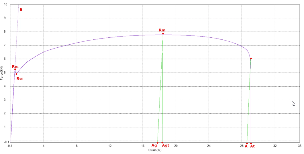
The output of the tensile test is a graph and a set of results describing the important events in the tensile test.
If we go through the individual results from the beginning of the test: there is a short run-up at the beginning of the test (jaw settlement, specimen alignment...) and then there is a linear part of the test which is more or less uninteresting in terms of results - the only interesting thing is its linearity. If the specimen is loaded, it is in this phase that the internal defects and slips at the grain level of the material are compensated for simplistically, the fibres in the material are broken), up to the point where the first drop in force (or stress) occurs.
ReH - upper yield strength - this highest point at the end of the line is referred to as the upper yield strength ReH. After this first drop in force, the specimen begins to elongate irreversibly (it has gone from elastic to plastic deformation). Engineers and computer scientists can plan the loading of the material up to the ReH value without any worries, because the manufactured part will not be damaged by the stresses. For safety reasons, of course, the designer stays away from this point when working with the material.
ReL - lower yield strength - the point on the curve after the first drop from the upper yield strength ReH, without including the surge. The overload is a visible (significant) decrease in force and is caused by the downward return (shrinkage) of the material and is greater than the subsequent force oscillation. This decrease does not affect the value of ReL. In the next section, the so-called Lüders region follows, where the force oscillates. In this region, the lowest force is sought and this is our search point - the lower yield stress ReL This is therefore the largest drop in stress in the Lüders region before the force starts to rise again.
E - elastic modulus; E-modulus; Young's modulus - all these meanings are synonymous. It is a value that is calculated using various methods - tangent, intercept, bowstring... i.e. a theoretical value that expresses, in effect, the slope of a straight line. All methods for calculating the elastic modulus E work with relative elongation (epsilon) and stress (sigma). One way of calculating the elastic modulus is by using the ratio of two points of the stress value obtained at 0.005% and 0.025% elongation. The modulus of elasticity is thus a calculated - not measured - value, which in turn is mainly appreciated by designers and engineers for calculations.
Rp 0.2 - contractual yield strength; for materials without a significant yield strength, the yield strength ReH is not visible, but the transition of the linear part starts to round off smoothly. The contractual yield strength Rp 0.2 (can also be Rp 0.1 or Rp 1.0 or other) expresses the stress value at 0.2% elongation.
Rm - strength limit - in the next phase of the tensile test, the material is strengthened (all internal material failures have been exhausted) and therefore the strength increases (after the Lüders region has been completed). The explanation for the strengthening of the material is simple: all problematic, internal defects have been exhausted and the internal structure of the specimen has equilibrated so that all structures in the specimen provide a common resistance to loading.
Therefore, at this point in the tensile test, there is a further increase in stress up to the point where the tensile specimen does not require any further increase in force during elongation, but begins to elongate without any increase in force or stress. Thus, the specimen material continues to elongate uniformly until a neck (initially small) begins to form at one point. The ultimate tensile strength is this maximum stress, beyond which the elongation continues to increase but the force or stress begins to decrease gradually. The ultimate stress is expressed in N/mm2 (the ratio of the maximum force to the cross-sectional area of the specimen) = Mpa.
At this point, a neck begins to form, the formation of which gradually accelerates until complete fracture occurs.
Ag - elongation at intermediate strength; Agt - as Ag, but including elastic percentage
In the further progression beyond the maximum stress, the force decreases until the point of fracture. At this point, the last important result is available, viz:
A - the relative elongation at fracture or At - the relative elongation at fracture including the elastic contribution.
This value can be obtained even without a strain gauge using a known formula, thanks to the lines made on the specimen before the test and the subsequent remeasurement of the composite specimen after the test.