Tensile test of plastics
The tensile test of plastics according to EN ISO 527
The tensile test is further divided into:
ČSN EN ISO 527-1 Plastics - determination of tensile properties - part 1: basic principles
ČSN EN ISO 527-2 Plastics - determination of tensile properties - part 2: test conditions for molded plastics
ČSN EN ISO 527-3 Plastics - determination of tensile properties - part 3: test conditions for films and plates
ČSN EN ISO 527-4 Plastics - determination of tensile properties - part 4: test conditions for isotropic and orthotopic fiber-reinforced plastic composites
ČSN EN ISO 527-5 Plastics - determination of tensile properties - part 5: test conditions for plastic composites reinforced with unidirectional fibers
Tensile testing according to EN ISO 527 covers the testing of a wide range of plastics - filled or unfilled materials, molded or cast samples, foils and plates, as well as fiber or binder reinforced materials.
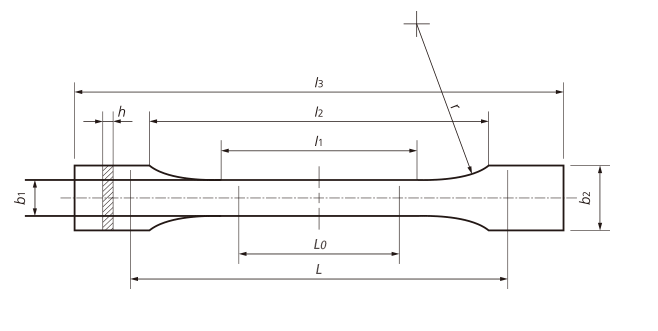
Tensile test specimens according to EN ISO 527-2 - the most commonly used
The mentioned standard specifies the type 1A shape for the injected test specimens and the type 1B shape for the machined test specimens. Type 1A and 1B test specimens are the preferred shape of test specimens, with the initial measured length set at 75 mm, which compared to the past (L0 = 50 mm) represents greater accuracy in modulus measurement and better utilization of the middle portion of the Type 1A specimen, which is 80mm long. An initial measured length of 50 mm is still permissible, but not recommended for the Type 1A test specimen.
- shape 1A and 1B are standard test specimens with comparable dimensions
- shape 1BA and 1BB are relatively reduced test specimens and can only be used if standard test specimens cannot be used
- shape bodies 5A and 5B are proportional test bodies with respect to ISO 37 (rubber testing standard), shape 2 and 3
- CW and CP shape test specimens (identical to ISO 8256 shape 2 and 4) are small test specimens intended for heat aging tests.
Before starting the tensile test
The tensile test of plastics is carried out on a loading machine - a tear machine.
In the first step, the specimen grips / clamps are set to a distance of 115 mm. Subsequently, the sample is clamped in the testing machine, and great care must be taken to ensure that the sample is loaded in all directions by uniaxial tension. It was found that the oblique clamping of the sample can affect the modulus by up to 4 %. At the same time, great care must be taken when clamping to avoid compressing the sample - measurements have shown a 3 % distortion of the module result if the sample was compressed before the test.
However, a small pre-load of the sample is necessary to avoid the "heel" of the curve. Preloading the specimen ensures an initial test starting point independent of the operator and test equipment. The test itself does not start when the machine is started, but when the set pre-load is reached. Max. the size of the pre-load should not exceed 0.05 % or when measuring strength, the preload value should be less than 1/100 of the stress value.
Test speed during the tensile test
The course of the tensile test was described in more detail in the chapter on the tensile test of metals.
Here for plastics, according to EN ISO 527-1, the determination of the modulus of elasticity should be achieved at a speed of 1 %/min. The speed of 1 mm/min then corresponds to the rate of elongation increase of
0.87 %/min.
It may seem strange, but the grips also play a big role in maintaining the correct test speed.
Similar to the tensile test of metal samples, the test speed can be increased after measuring the E-modulus. In practice, 5 mm/mm or 50 mm/min is often used.
However, as discussed earlier: the achievement of correct and reliable results does not begin with the actual performance of the tensile test, but with the production of the tensile test specimen itself. Production must be accurate and in accordance with the standard.
Requirements for tensile testing according to EN ISO 527
- ISO 7500 class 1 burst test machine
- clamping devices, grips corresponding to the material and sample size
- according to the budget, then an extensometer
A hand-held extensometer - usually with a small stroke for determining the E-modulus - cannot, however, be used for foils
Automatic strain gauge - for determining E-modulus and also ductility at max. tension as well as ductility at break
Non-contact video-extensometer - for determining the E-modulus as well as ductility at max. tension as well as ductility at break using lines on the sample itself
EN ISO 527 tensile test output
The output of the tensile test is a graph and a set of results describing important events during the tensile test.
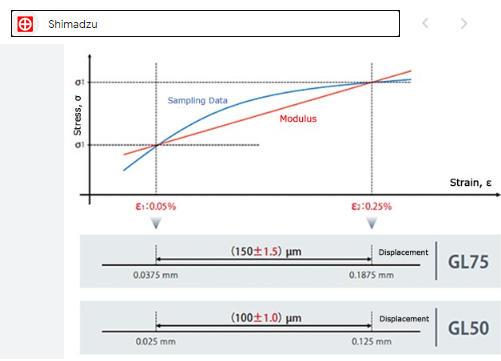
Similar to the metal tensile test, the most important results are obtained at the beginning of the test, where a lower test speed is therefore used. In the case of plastics, however, linear loading does not have to occur, which is why, for example, sectioning is used to determine the E-modulus.
E - modulus of elasticity; E-module; Young's modulus - this is a calculated value, but based on measurements. Most often, two points are used, which can be constructed by cutting. The secant intersects the curve at the point where the elongation reaches values of 0.05 % and 0.25 %. This method is very simple, but it is sensitive to the data obtained - because it only works with two points. Alternatively, you can also use the regression line, which uses all points to calculate the E-module. This is therefore a statistically more accurate method of determining the E-module.
σy / εy - contractual yield strength - for materials with a significant yield strength, this is the highest point on the curve, followed by a decrease, so that the strength / strength increases again up to Fmax.
σx - stress at a certain elongation - for materials without a significant yield point, the yield point is not visible, but the transition of the linear part begins to smoothly round off. The yield strength σx (can be at 1 %, 2 % or other elongation) expresses the stress value at a given elongation.
σm - ultimate strength - in the next phase of the tensile test, there is a further increase in force, up to the point where the tensile sample does not require any further increase in force during elongation, but begins to elongate without an increase in force, i.e. stress. Thus, the sample material is elongated uniformly further until a neck (small at first) begins to form at one point. The strength limit of the tensile stress is precisely this maximum stress, after exceeding which the elongation continues to increase, but the strength or the voltage begins to slowly (or suddenly) decrease. The tension between strengths is expressed in N/mm2 (proportion of max. force per cross-section of the sample) = Mpa.
At this moment, a neck begins to form, the formation of which gradually accelerates until a complete fracture occurs.
εm - elongation at break strength
σB / εtB - stress / elongation at break
In the further course, beyond the maximum stress, the strength decreases until the moment of fracture. At this moment, the last important result is available.